


Buy anything from 5,000+ international stores. One checkout price. No surprise fees. Join 2M+ shoppers on Desertcart.
Desertcart purchases this item on your behalf and handles shipping, customs, and support to Italy.
🔋 Power Up Your Projects with Precision!
The 10 Pieces 5V Regulator Module is a versatile voltage reducer designed for a wide range of applications. With an input voltage range of DC 4.5-24V and adjustable output options, this module ensures high efficiency and reliable performance. Its compact design and durable materials make it an essential tool for any DIY enthusiast or professional engineer.
| ASIN | B08JZ5FVLC |
| Additional Features | Short Circuit Protection |
| Amperage | 3 Amps |
| Best Sellers Rank | #98,571 in Tools & Home Improvement ( See Top 100 in Tools & Home Improvement ) #364 in Power Converters |
| Brand | Weewooday |
| Built-In Media | 10 x Mini 5v regulators |
| Color | red |
| Compatible Devices | [INFERRED] Devices with a 5V input requirement |
| Compatible Phone Models | [INFERRED] Devices with a 5V input requirement |
| Connectivity Technology | Proprietary Connector |
| Connector Type | Proprietary |
| Current Rating | 3 Amps |
| Customer Package Type | FFP |
| Customer Reviews | 3.0 out of 5 stars 251 Reviews |
| Enclosure Material | Electronic components and materials |
| Frequency Range | 500 KHz, NO |
| Included Components | 10 x Mini 5v regulators |
| Input Voltage | 24 Volts |
| Item Weight | 22.68 g |
| Main Power Connector Type | 2 Pin |
| Manufacturer | Weewooday |
| Mfr Part Number | Weewooday-820 |
| Model Number | Weewooday-820 |
| Mounting Type | Board Mount |
| Number of Items | 10 |
| Number of Power Levels | 6 |
| Output Current | 3 Amps |
| Output Voltage | 5 Volts |
| Portable | Yes |
| Power Plug | No Plug |
| Power Source | Battery Powered, Corded Electric |
| Special Feature | Short Circuit Protection |
| Specification Met | CE |
| Unit Count | 1.0 Count |
| Wattage | 693 watts |
D**D
Awesome little buck converters
There are a few bad reviews on this item, but I have purchased this buck converter several times and I have been happy with every single one of them. Perhaps the documentation is insufficient or missing, but if you're buying one of them you probably at least THINK you know what you're doing, and when the negative reviewers connected it wrong and it short circuited, they decided to blame the device for their misuse. Connections: On one end of the chip there are 4 solder pads that are labeled VO+, GND, IN+, and EN. VO+ = the positive output pin (stepped down to whatever you select) IN+ = the positive input pin (acceptable range between 4.5V and 24V) GND = shared/common ground for your input and output (e.g. BOTH input and output negative grounds are connected to this one, single pin). EN = enable port (e.g. used to turn power on or off like a relay) Unless you plan to use a GPIO pin (Arduino, RPi, etc.) to signal the enable port (e.g. to turn power on/off), just ignore the EN pad. If you do want to power it on and off, connect a GPIO pin to the EN pin and set the GPIO to HIGH to STOP power flow through the chip and LOW to turn it ON. I typically don't use the EN port for my projects, but it's a nice feature. Note: If you wire the EN pin as a ground for your voltage in (which is likely what the bad reviewers did), it will short circuit. Don't do that and then complain that the chips are bad - they're not; you just wired it incorrectly. The EN port is NOT a ground. Voltage selection: The trickier part is voltage selection. Remember, this is ONLY a voltage reducer. If you feed it 4.5V, you can't get 12V out of it. Your desired output voltage must be LOWER than your input voltage. Also, BY DEFAULT, the potentiometer on the top of the chip is what is used to adjust the voltage. If you prefer to use the solder pads on the back to step down to a pre-defined voltage, you have to cut the connection on the ADJ jumper pad that is connected on the printed circuit board (the connection you need to cut is under the green shielding). Cutting this connection is probably the most difficult thing to do on the device. An X-Acto knife works well for it, but it takes some effort to cut all the way through the connection without cutting your finger (ask me how I know). For the sake of safety, I typically adjust the potentiometer using a power supply for my power input and a voltmeter to check the voltage output. Depending on the project, once I have everything soldered and adjusted, I typically use a piece of adhesive-filled heat shrink tubing to cover the entire chip. This will: 1. lock in the potentiometer setting and 2. seal everything up nicely to keep it waterproof.
A**N
DO NOT BUY THESE
I bought these despite some of the other reviews, hoping that even if I lost a couple to bad QC, the ones that worked would be fine. Wrong. From a usability standpoint, it's hard to tell where to cut the trace for the fixed voltage output. Very difficult to use for that reason alone, but of the batch I got, 60% smoked the IC immediately when applying power to them or tripped the OCP on my bench supply set to 200mA (so, dead shorted internally), regardless of voltage setting or input. The remainder shut down at anywhere from 14-18v input, far below the claimed 24v. Long story short, horrible design, and pure junk that doesn't work as advertised, even when it does at all.
A**K
Works great, remember to cut the little strip by the ADJ pad.
Seems like a few of the people who have issues with this haven't figured out what the "cut the line in the red frame" mean. The top pad, where it says ADJ, if you look really really closely, has a very thin strip connecting the pad. If you leave that, the other pads won't give the correct voltage, and it will only work with the ADJ wheel. Just take a razer, or any thing sharp and pointy, and cut that little line, and it will suddenly start giving you the right voltage. I find these super compact, and really easy to put into any project that needs a constant flow of power at a set voltage. So I can send 3.3V to my ESP8266 board, and 12 volts to my relays, all with one power source.
J**W
10 of 20 burned out more or less instantly
I bought 80 of these (8 packs of 10) for a project where I need 60 of them. Of the first five, the first three cooked within seconds of being energized for testing. Maybe some of that was my fault, like I touched something with a probe or something. I'll be the first to blame user error. Then a few more burned out as I was being VERY careful with them not to short anything by mistake. Some I had set to 3.3V got really hot. Multimeter had a tough time measuring the voltage on some of them, but if I just held the probes on the output for long enough it'd eventually read 3.3v consistently. 5V seemed to do a little better. I assembled a device with five of these - four at 5 Volts and one at 3.3 and carefully brought up the supply voltage. No loads attached at this point, just verifying they were supplying safe voltages. Current draw was pretty acceptable at 60mA for all five. I couldn't quite force myself to energize this unit with a full 12V under the actual load of use - about 1A each of the 5V and 300mA on the 3.3V. Something about it gave me the creeps. So, I very carefully assemble another setup with four 5s and a 3.3. I'm especially careful to solder everything independently and make sure all is very clean and the process is clearly thought out and protects the converters from excessive heat or unwelcome touching. I connect the all the loads. I hook it up to a different 12V power supply. Flames immediately flare out of three of the five volt converters. One 5V appears not to have burned out, and the one set to 3.3V also seems ok visually. You can see exactly which component died in all cases. I don't dare to try any more of these, lest they destroy the components they're supposed to be powering. I'm still sitting on 60 of these things, so I figure - before I push go on this one-star review, let's do one more test. I hook it up and run it up to 12V. It seems to want to spit out a nice 5V. On the oscilloscope, the output is good. But it randomly gets really hot, and my whole workshop smells like burned out electronics. I just don't trust them anymore. I'm sitting right around a 50% failure rate with the legitimate potential to start a fire. This is by no means a sterile laboratory environment, and I bought an extra 20 because I figured I'd make a mistake here or there. But I'm not THIS incompetent. I'm not going to attempt to use these converters further. Bought 15 chunkier 5V 10A regulators instead and will share the load from one regulator instead of relying on four smaller ones. I'll just hook up an LDO regulator to pipe down to 3.3V from the 5V rail. I doubt the 25% of reviews with one star would have deterred me from making the purchase. I love a good adventure, after all. This is one of those rare times where whatever I just bought is utterly unfit for a task for which the product description clearly said it would be well suited. If you're smarter than me, you'll avoid these. Or maybe your extra wit will enable you to use them successfully. Good luck!
B**C
Handy little device, with design limitations
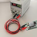
This switchmode regulator module was quite useful in replacing a linear voltage regulator to reduce the current draw of my design, but it is not a "drop in" replacement. I had to make several changes in my design (due to ripple effects) and I had to modify the module to get the output voltage accuracy I required. My design is battery powered, 12V nominal. Much of my design runs straight off this 12V supply, but some circuits in the design require 5.00V +/-10mV @ 100-150mA. For purposes of testing, I used a 40Ω resistor to load the output of the switchmode module at 125mA. I have tested only two of the 10 modules I received, but both worked well. No functional problems. I first tried to use the adjustment pot to set the voltage accuracy I required. No joy. The pot is very sensitive. The slightest movement of the slider produced at least a 50mV change in the output voltage. I decided I had to use the fixed resistors. However, during this testing, I noted two problems. The photo sows the voltage ripple and the switching frequency of the switchmode regulator. The vertical scale is set to 20mV/div and the horizontal scale is set to 2us/div. The ripple is 60mVpp and the switching period is 6.4us, for a frequency of 156kHz, not the 500kHz claimed by the seller. During this testing, I briefly turned the output voltage up to 10V, which increased the output current to 250mA. The switcmmode control chip got quite hot. I did not measure the temperature. However, if your design will draw 500mA or more, you really should investigate this temperature rise. I truly would be surprised if this module can deliver 1.5A of output current without special measures for cooling, as claimed by the seller. My next step was to cut out the trim pot and used the 5V fixed resistor. The first module delivered 5.077V. That is 1.5% accuracy, which really isn't bad. The second module delivered 5.105V. I realized that I was unlikely to find a module that gave me the 5.00V +/-10mV that I required. So I unsoldered the fixed resistor for a 1.8V output (on the first module) and replaced it with a 2MΩ resistor (both 0603 size, which are fun to work with). I then also bridged the pads for that resistor, which put it in parallel with the 39kΩ resistor for a 5V output. The output voltage dropped to 4.996V - well within my requirement. The 60mVpp ripple caused severe problems for a voltage comparator circuit. This circuit drew only 1mA, so I added a simple RC filter (10Ω, 10uF) in the 5V supply for this circuit, and adjusted the resistor values in the reference voltage divider to account for the 10mV voltage drop. Problem solved. The 27uF (?) input capacitor on the switchmode regulator still allowed a significant ripple current in the 12V supply line. Perhaps because of resistance in the battery, this created ripple on the 12V supply for the entire design, causing problems. I added a 47uH inductor in the 12V supply to the switchmode regulator, which solved that problem. So, I am glad this switchmode regulator module was available, and using it it did extend my battery life by about an hour and a half. But using this regulator in place of a linear regulator brings its own set of problems with it. Design with care.
M**T
Works fine for me
Was concerned when I saw a few spotty reviews. Lack of printed instructions was a pain. Found out the basics from a review here and all good after that. I am using it to run 6 model aircraft servos from a pair of 18650’s and so far it’s fine. Even though I see 3A peaks now and then during 6 servo runs in random motion it doesn’t seem to be heating appreciably. You may see different results from using it as a motor controller with a higher duty cycle. My setup is 8.4v nominal to 5V Vin is source positive Vout is regulated output Gnd is common ground for both En is enable, I leave it floating Apparently the different voltage pads are only functional if you enable them by cutting a trace then bridging the pair you want with a solder dab. The potentiometer trims the voltage. I run mine via the three signals noted above and tune the potentiometer. No use of the separate voltage pads. Done So far so good, small and great price
K**N
Don’t work
This product did not work. I tested 10 units, and all of the power supplies were defective. Based on my experience, I would not recommend purchasing it.
J**D
works but very delicate
I blew up two of them getting things hooked up. Not just one. But I didn't wire anything wrong. I had the power supply at 13.6 volts with a 0.250 amp current limit on it and just attached the leads to the module. It seems like the microarc that occurs at the moment the leads make contact was enough to blow out the input levelling capacitor. The potentiometer is very sensitive and the voltage regulation based on the pot setting varies several tenths of a volt depending on the load. Since I haven't been using them for a long time, I don't know what the longevity of them will be in actual circuit conditions, but I have no reason to think that will be a problem. OK, so I looked at some of the other reviews. And it kind of seems like a lot of people are blowing them up with mistakes and whatnot and then saying that they are bad. But, my view is that really these modules are just very delicate and easy to destroy. I mean like perhaps the input capacitor has a 15V rating or something which is just way to close to the operating input voltage. Dunno. Time will tell whether they last or not.
D**C
Faulty Boards?
We've used a virtually identical board previously without issue. These boards burn up instantly. V+ in is 12VDC, we used the default adjustable setting with no cuts or jumpers, EN is left unconnected. The small 8 pin glows a nice bright orange for a few seconds. Tried two boards just to verify and double check, both burned. We had a small load for ~100ma and a configured test jig used for previous boards.
Trustpilot
1 week ago
1 week ago